Step-by-step assembly for the D-12 — a faithful recreation of the AKG C12 tube condenser circuit. Synthesized from community builds and the official D-12 Assembly Guide.
01
Before You Start
Separate the PCB from the panel by breaking the tabs gently — score the tabs with a blade first, then snap cleanly. File any rough edges.
Inspect both sides under good light: verify no lifted pads, cold solder bridges from fabrication, or damaged traces.
Read this entire guide and the Errata section before placing a single component.
Confirm tools: temperature-controlled iron (25–40 W, fine tip, ~680 °F / 360 °C), 0.7–1.0 mm rosin-core solder, multimeter, 91 % IPA, clean acid brush, alligator-clip heat sink, nitrile gloves.
Initial clean: wipe both PCB faces with 91 % IPA on a lint-free cloth. Air dry completely.
⚠️ High-impedance handling throughout this build
The D-12 circuit contains resistors up to 250 MΩ and nodes at extremely high impedance. Finger oils, flux residue, and contamination on these components or their solder joints permanently degrade noise performance. Nitrile gloves are required for Steps 3, 4, 5, and 14. Never touch high-Z resistor leads with bare hands.
⚠️ Styroflex capacitors are heat-sensitive
C10 and C11 are polystyrene (styroflex) capacitors. Heat damage is invisible at build time but causes intermittent failures later. An alligator-clip heat sink is mandatory for these components — see Step 4.
▶ 💡 Tools checklist
Tools: 25–40 W temperature-controlled iron with fine tip, 0.7–1.0 mm rosin-core solder, alligator-clip heat sink, side cutters, tweezers, needle files, multimeter, 91 % IPA, lint-free cloths, nitrile gloves, small Phillips screwdrivers.
Note: Acetone and aggressive solvents dissolve polystyrene. Use only 91 %+ IPA for cleaning. Never apply IPA directly to installed styroflex caps.
02
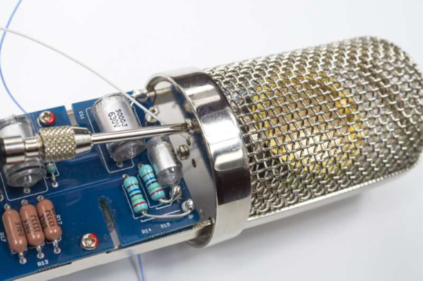
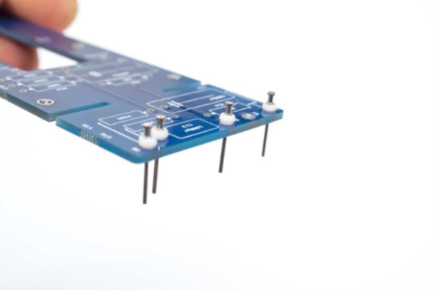
Install PCB Turrets
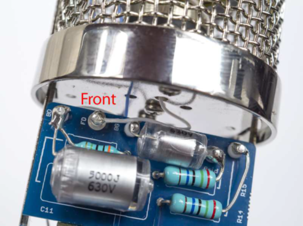
Five turret positions: BD (Back Diaphragm), BG (Backplate 2), BP (Backplate 1), Grid, FD (Front Diaphragm). These form the high-impedance connection points for the capsule and tube grid.
FD turret — press squarely into padSolder flush; minimum iron contact
Five turret positions: BD (Back Diaphragm), BG (Backplate 2), BP (Backplate 1), Grid, FD (Front Diaphragm).
Press each turret fully into its PCB hole using a turret tool or drill press — never hammer. The flange must sit flat against the PCB surface.
Solder from the component side only. Use minimum heat and minimum solder — these are high-impedance nodes.
Inspect each turret for mechanical squareness. A tilted turret will cause wire-routing problems in later steps.
⚠️ Nitrile gloves on from this step
The turret pads are part of the high-impedance front-end. Any finger oils introduced now will be impossible to clean after capsule wiring is complete.
03
Install Resistors
Install resistors in three groups, from lowest to highest impedance. The high-Z resistors in group 3 require the most care — clean iron tip, minimum flux, no excess heat.
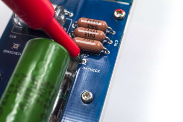
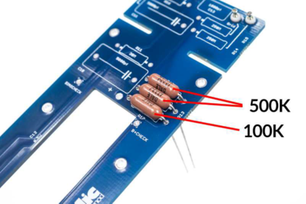
Group 1: R12, R13 (500 kΩ), R17 (100 kΩ). Standard metal-film resistors — install in either orientation.
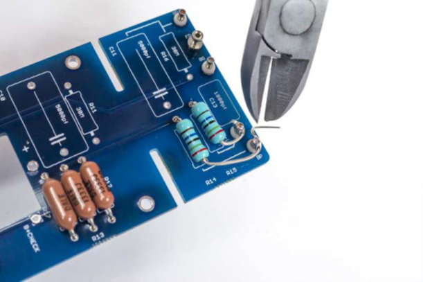
Group 1: R12 = 500 kΩ, R13 = 500 kΩ, R17 = 100 kΩ. Standard 1 % metal-film resistors. Install in either orientation. Trim leads flush after soldering.
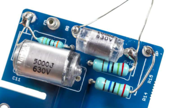
Group 2: R14, R15 (250 MΩ). High-impedance — handle with gloves; use minimal flux.
Group 2: R14 = 250 MΩ, R15 = 250 MΩ (backplate bias resistors). Nitrile gloves required. Install with minimum flux. Clean joints with IPA on a fine brush immediately after soldering.
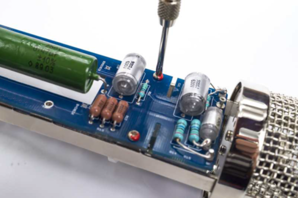
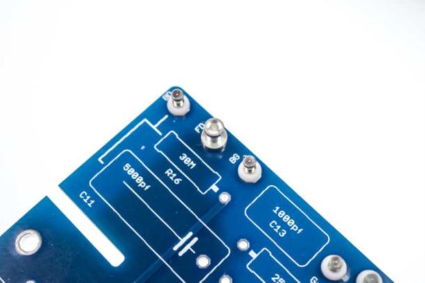
R11, R16 (30 MΩ) — grid leak and front-diaphragm biasVerify clean, shiny joints — no excess flux
Group 3 — critical: R11 = 30 MΩ (grid leak), R16 = 30 MΩ (front-diaphragm bias). These are the most sensitive resistors in the circuit. Gloves on. Clean the iron tip immediately before soldering. Apply heat for the minimum time needed to achieve a shiny joint. Use the smallest possible amount of flux. Inspect under magnification.
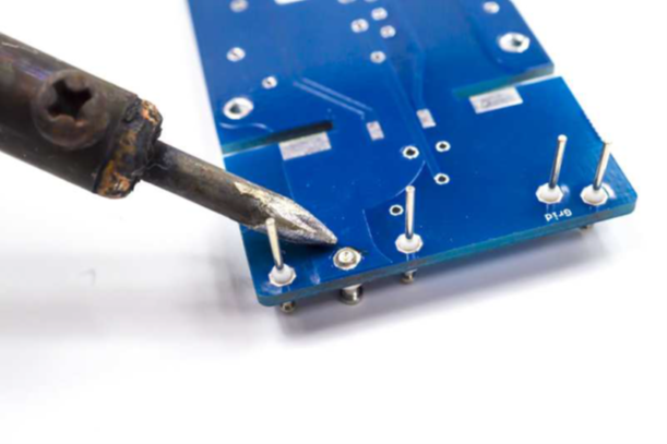
3.4 — Back-side components: Populate any remaining components specified on the PCB reverse side (refer to the silkscreen). Follow the same high-Z precautions for any back-side pads near the turret area.
⚠️ No excess flux near high-Z resistors
Flux contamination on R11, R14, R15, R16 leads or their pads creates leakage current paths that permanently raise the noise floor. If excess flux is present, clean immediately with 91 % IPA on a cotton swab — then air-dry fully before proceeding.
04
Install Styroflex Capacitors (C10 & C11)
C10 and C11 (5000 pF polystyrene). Alligator-clip heat sinks clamped on each lead between the capacitor body and PCB — mandatory.
C10 = 5000 pF, C11 = 5000 pF (both polystyrene / styroflex). Non-polarized — install in either orientation.
Heat sink mandatory: clamp an alligator clip on each lead between the capacitor body and the PCB pad, component side. This absorbs heat before it reaches the dielectric.
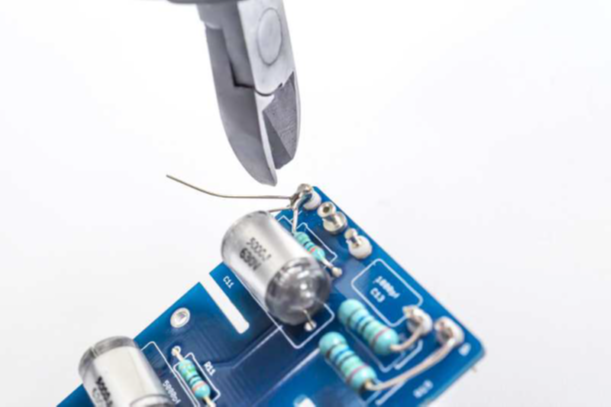
Solder from the underside. Touch the iron to the pad for no more than 2–3 seconds. Remove heat immediately when solder flows.
C11 — turret-to-turret: C11 bridges the BG turret ↔ Grid turret directly. Keep the leads short and route flat against the PCB to avoid stress on the turret joints.
After soldering, inspect the capacitor body. Any discoloration, shrinkage, or warping indicates heat damage — replace before continuing.
⚠️ Polystyrene capacitors cannot tolerate heat or solvents
The dielectric dissolves in acetone and melts at soldering temperatures if heat sinks are not used. Never apply IPA or any solvent directly to these capacitors once installed. Heat damage produces intermittent pops and crackle that appear weeks after the build.
▶ 💡 Alligator-clip technique
Clamp the clip as close to the PCB as the lead geometry allows. For C11 (turret-to-turret), solder one end first — let it cool fully before soldering the second end. Round-robin between leads if the first joint is still warm.
05
Clean the PCB — Do Not Skip
Clean every joint and pad in the high-Z area — turrets, R11, R14, R15, R16 and their surroundings. Air-dry for at least 10 minutes before proceeding.
Clean both sides of the PCB with 91 % IPA on a clean acid brush. Work systematically across the entire board surface.
Pay particular attention to the high-impedance area: all turret bases, R11, R14, R15, R16 and their solder joints.
Do not apply IPA directly to C10 or C11 — the solvent damages polystyrene dielectric. Work around them carefully.
Air dry completely — minimum 10 minutes at room temperature. Do not use heat to speed drying on a board with styroflex caps installed.
After drying, inspect all joints under a magnifier. Any residue or cloudiness in the high-Z area must be re-cleaned.
⚠️ This step is mandatory — not optional
Flux residue left on the board after this step will be impossible to remove without disassembling components. Contamination in the high-Z area will cause elevated noise floor, intermittent crackling, and sensitivity loss. This step cannot be performed later.
06
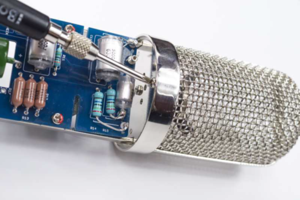
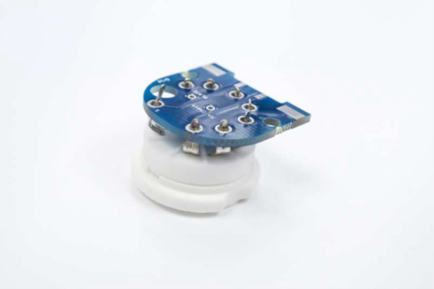
Install Tube Socket
9-pin noval tube socket installed. Solder all pins; verify the socket sits flat and square before soldering the remaining pins.
Identify the 9-pin noval socket orientation — the key pin or locating tab must align with the silkscreen indicator.
Insert the socket and tack-solder two opposite pins. Verify the socket sits flush and square against the PCB. Correct any tilt before proceeding.
Solder all remaining pins. Use standard heat time — this area is not high-impedance. Trim any excess lead length flush.
Verify all 9 pin positions are soldered. A missed pin can cause intermittent failures that are difficult to trace.
07
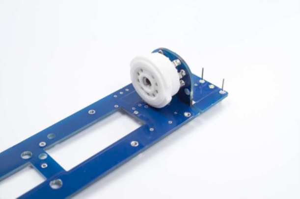
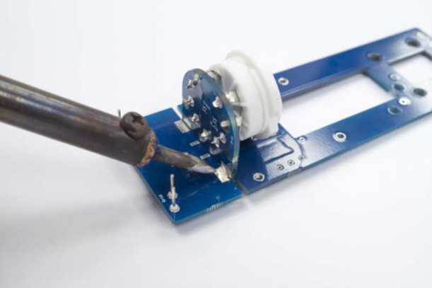
Join PCB Assemblies at 90°
90° join — dry-fit first to verify alignmentFinal solder joints at both faces of the join
Dry-fit the two PCB sub-assemblies together at exactly 90° before soldering. Verify all connector pins are fully seated and the mechanical alignment is correct.
Tack-solder two pins first. Recheck the 90° angle — once all pins are soldered, correction is destructive.
Solder all remaining connector pins from both accessible faces. Inspect each joint for good wetting and correct seating depth.
After soldering, verify mechanical rigidity of the join. Any flex indicates an insufficiently soldered joint.
08
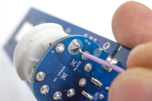
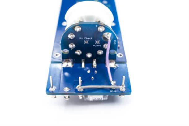
Grid Wire & BG↔BP Link
Grid wire: 2.5 cm — socket Grid pin → Grid turretBG↔BP link: 2 cm wire between turrets
Grid wire: Cut a 2.5 cm length of thin, unshielded wire. Solder one end to the Grid pin of the tube socket; the other end to the Grid turret. Keep the wire short and routed flat.
BG↔BP link: Cut a 2 cm length of the same wire. Bridge the BG turret to the BP turret. This connects the two backplate nodes together as required by the circuit.
Use only thin, unshielded wire for both connections. Shielded wire adds parasitic capacitance that attenuates capsule signal — see FAQ.
Keep both wires as short as possible. Dress them flat against the PCB surface to minimize stray capacitance.
⚠️ Never use shielded wire on any turret connection
Shielded wire in parallel with the capsule creates a capacitive voltage divider that severely attenuates output. Even a short run (2–3 cm) of shielded wire at a capsule node can reduce output by 20+ dB. Use only plain thin stranded wire throughout.
09
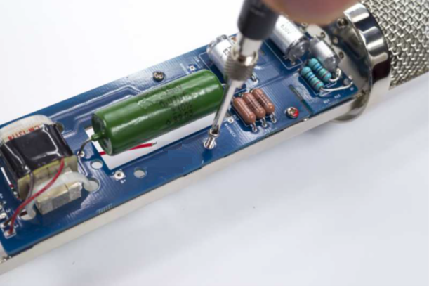
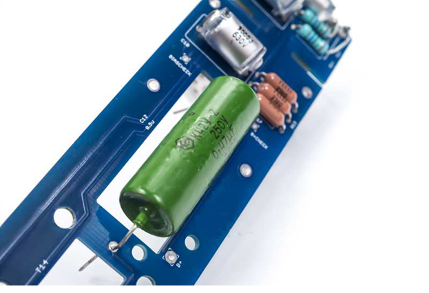
Output Capacitor (C12)
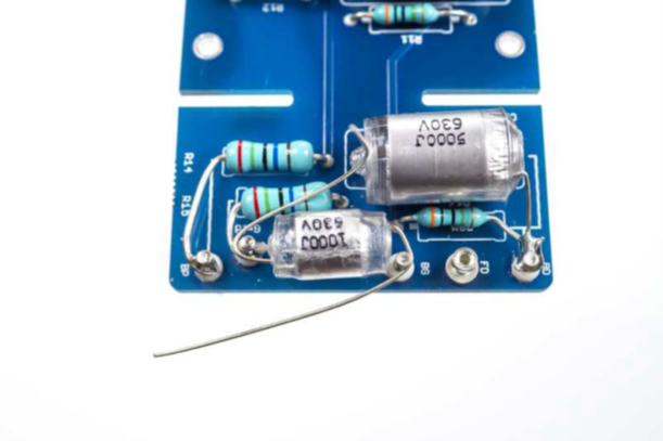
C12 — the output coupling capacitor. Two options are available; choose one before installing.
Option A — 0.47 µF NOS K42Y-2 PIO (Paper-in-Oil): Vintage-voiced character. Slightly rolled-off low end, forward and present. Recommended for the classic C12 tonal balance.
Option B — 1.0 µF polypropylene: Extended bass response, slightly slower transient character. Choose if maximum low-frequency extension is a priority.
C12 is non-polarized — install in either orientation. Verify the value before soldering.
C12 sits between the output transformer and the tube plate — it is in a moderate-impedance section of the circuit and does not require high-Z precautions.
▶ 💡 Which option to choose
The K42Y-2 PIO (Option A) is the canonical choice for an authentic C12 sound and is what most builders use. Option B produces objectively more bass extension but at the cost of some transient definition. If this is your first build, use Option A.
10
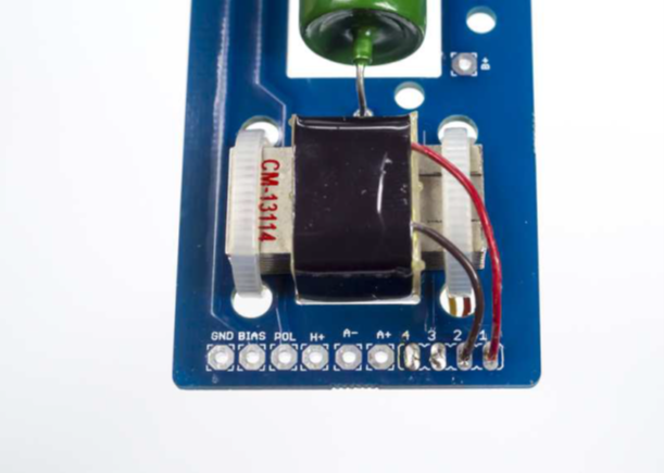
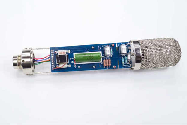
Output Transformer (Cinemag CM-13114)
CM-13114 secured with zip tieRed=Pin 1 (primary), Brown=Pin 2Orange+Yellow (secondary) route to back
Before wiring: use a multimeter to measure DC resistance of both wire pairs. The high-resistance pair (~1.5 kΩ) is the primary — it connects to the PCB. The low-resistance pair (~300 Ω) is the secondary — it connects to the 7-pin XLR.
Mount the transformer body with a zip tie through the PCB eyelet. The transformer must be mechanically secure before wiring.
Primary connections: Red = Pin 1, Brown = Pin 2. Connect to the primary (high-resistance) PCB pads.
Secondary connections: Orange and Yellow. These route to the back of the assembly for later connection to the 7-pin XLR (Step 13).
⚠️ Errata E26 — transformer primary/secondary reversal causes low output and high noise
Swapping primary and secondary results in very low gain and elevated noise. Always verify winding resistance before wiring. Primary (to PCB) ≈ 1.5 kΩ; secondary (to XLR) ≈ 300 Ω. See Errata E26.
11
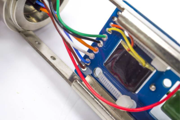
7-Pin XLR Connector
Pre-cut wires with correct lengths for each pin. The chassis ground must bond pin 7 to the XLR connector body before any other connections are made.
Chassis ground first: solder a direct wire from Pin 7 to the XLR connector body lug. This is mandatory for hum rejection and pattern-switch voltage integrity.
Pre-cut and strip wires to the lengths specified below before soldering to the connector pins.
Pin
Wire colour
Length
Signal
1
Red
8.5 cm
B+ (high voltage — insulate carefully)
2
Orange
4.5 cm
H+ (heater positive)
3
Blue
4.5 cm
Bias (−1 V grid bias)
4
White
4.5 cm
POL (polarization — pattern switch)
5
Black
4.5 cm
A− (audio −)
6
Green
4.5 cm
A+ (audio +)
7
Brown
4.5 cm
GND (0 V / chassis)
⚠️ Pin 1 (B+) carries ~120 V DC — insulate with heat-shrink
The B+ wire connects high voltage directly from the PSU. Use heat-shrink tubing over the solder joint and ensure no exposed conductor can contact the mic body or adjacent pins.
▶ 💡 Wire gauge for heater and ground
The heater line (Pin 2, H+) and ground return (Pin 7, GND) carry the highest current. Use 20 AWG for these two wires if your cable has separate gauges. All other pins carry negligible current — 26 AWG is sufficient.
12
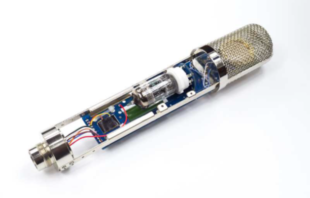
Install PCB into Body
Insert from top — align PCB to body railsTop: 2 screws; Bottom: short left, long right
Insert the PCB assembly carefully into the microphone body, aligning the PCB edges with the body rails. Do not force — the assembly should slide in smoothly.
Secure with the top two screws first. Verify the PCB is seated squarely before installing the bottom screws.
Bottom screws: the short screw goes on the left; the long screw goes on the right. Using the wrong length will either strip the threads or leave a protruding post.
Tighten to firm contact — do not overtighten. The PCB must be secure but the body must not deform.
13
Connect XLR Wires to PCB
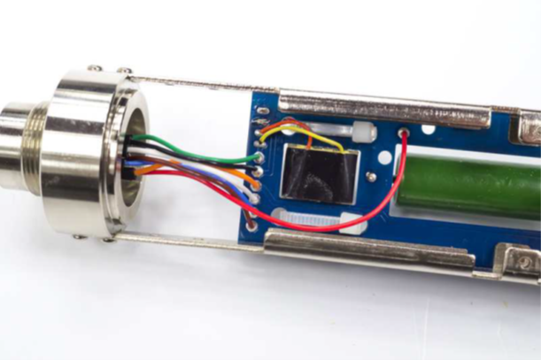
Route wires to PCB padsB+ connects between transformer and C12All wires connected and dressed
Connect each XLR wire to its corresponding PCB pad, following the wire colour table from Step 11.
B+ (Pin 1, Red): connects to the node between the output transformer primary and C12 — not directly to the transformer. Locate this pad carefully before soldering.
After all connections are made, dress the wires neatly inside the body. Ensure no wire is under mechanical stress or pinched by the body seam.
Double-check that the Pin 4 (POL) wire is isolated from the Pin 7 (GND) wire. Contact between these two pins is a critical fault — see Errata E27.
⚠️ Verify Pin 4 (POL) cannot contact any ground
Pin 4 carries the pattern-switch polarization voltage (0–120 V depending on pattern). Any accidental ground contact locks the mic in omni and may damage the PSU. Inspect every connection visually after wiring.
14
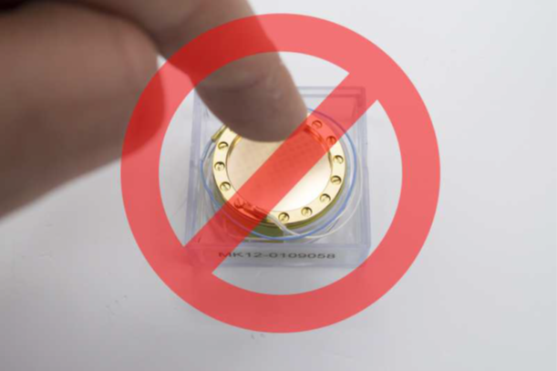
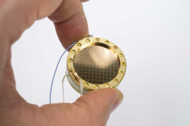
Capsule Installation
⚠️ Most critical step of the entire build
The capsule diaphragm is irreparably damaged by finger contact, dust, flux residue, solder splash, or breath condensation. Gloves on throughout. Never touch the diaphragm surface. Keep the membrane covers in place until the moment of installation.
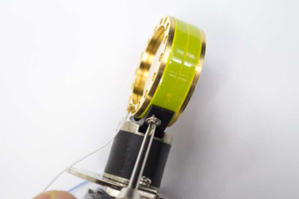
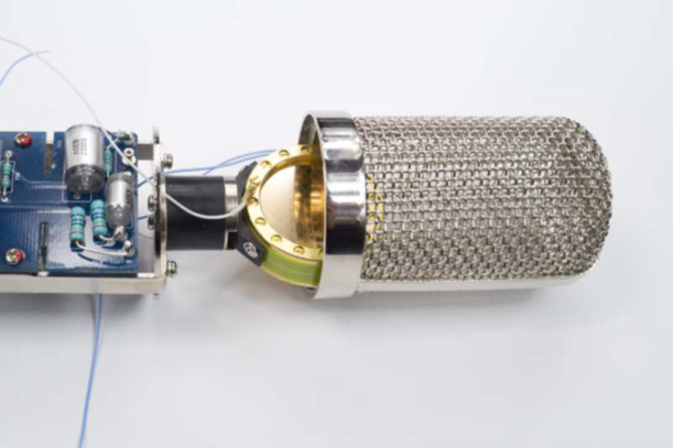
14.1 — Mount the capsule.
Capsule positioned in mount — handle by rim onlyFront orientation confirmed before securing
Tighten to firm contact only — not beyondVerify square seating after mounting
Orient the capsule correctly: for CK12-type capsules, the front is the side with three larger screws. For Tim Campbell CT12, follow the marked orientation on the supplied covers.
Mount with blue wire to the left as you face the capsule from the front.
Tighten mounting screws to firm contact only — do not overtighten. Overtightening distorts the capsule housing, permanently damaging the backplate geometry. See Errata E28.
After mounting, recheck that all screws remain snug — soldering heat from the next step can loosen them.
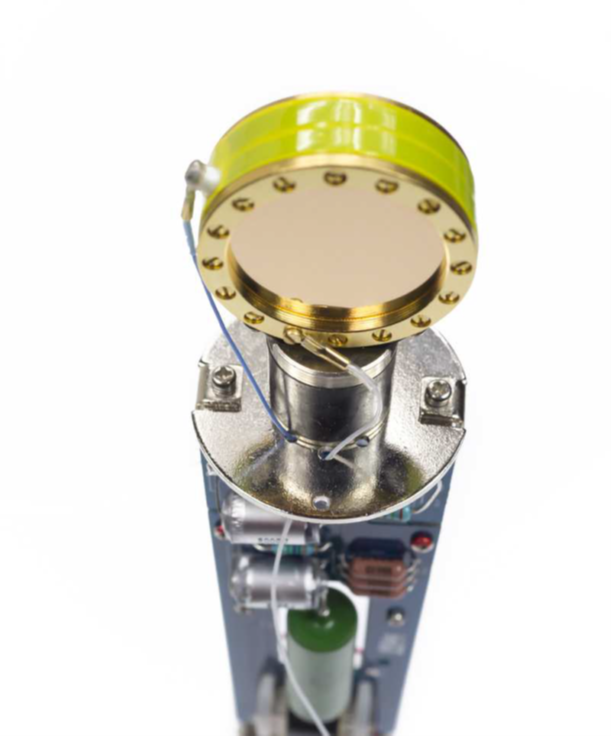
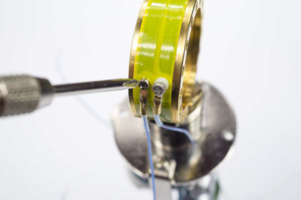
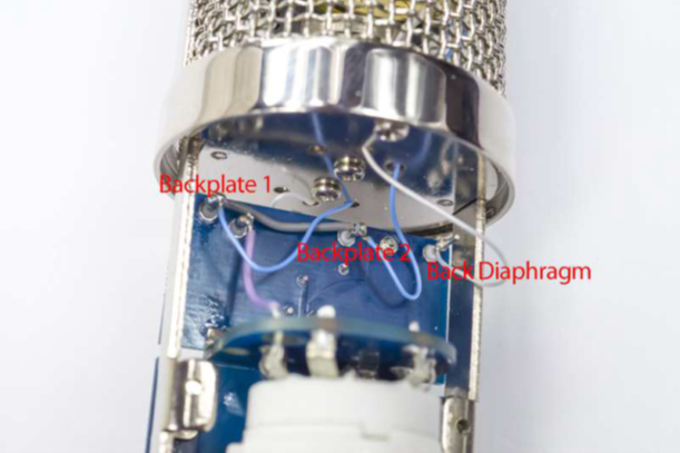
14.2 — Wire the capsule.
Front white → FD turretRear white → BD turretFront blue → BP turret
Rear blue → BG turretAll four wires connectedDress wires — no tension, no contact
Capsule wiring assignment (standard CK12 / CT12 with blue wire to left):
Front white → FD turret
Rear white → BD turret
Front blue → BP turret
Rear blue → BG turret
Use minimum heat and minimum time when soldering to capsule terminals. Pre-tin wires before bringing them to the capsule.
Keep capsule wires as short as possible — but with enough slack to avoid mechanical stress. Dress wires so they cannot contact each other or the body.
After wiring, check that all four mounting screws are still snug.
14.3 — Reassemble the headbasket over the capsule. Keep membrane covers in place until the basket is closed. The basket provides essential electrostatic shielding.
15
Tube Installation
Insert the tube gently with correct orientation. The tube key slot must align with the socket key. Never force.
The D-12 uses a 12AY7 or GE 6072A tube (9-pin noval, single-sided key).
Locate the key pin gap on the tube base. Align it with the socket key slot before applying any downward pressure.
Insert gently with a slow, even downward push — do not rock or force. The tube should seat with a soft click. If resistance is felt, re-check orientation before continuing.
Verify the tube sits fully seated and level in the socket. A partially-seated pin causes intermittent contact, which can damage the PSU.
💡 Tube orientation matters
The 12AY7 / 6072A has a locating key. Forcing the tube in the wrong orientation will bend pins and may damage the socket. Always verify alignment before pressing down.
16
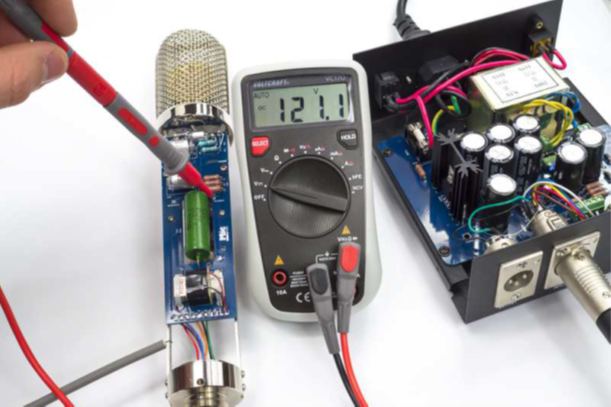
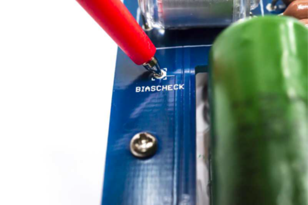
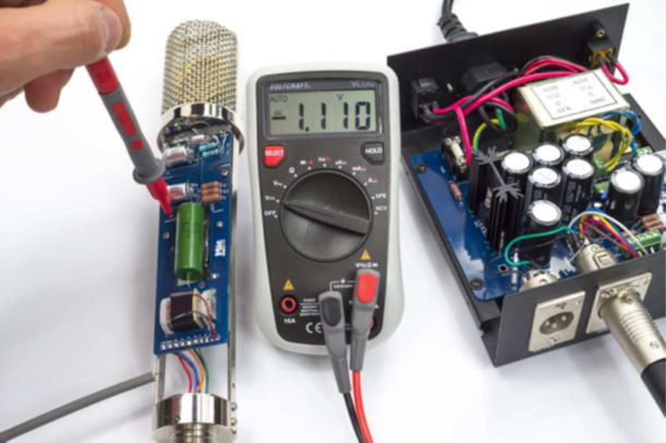
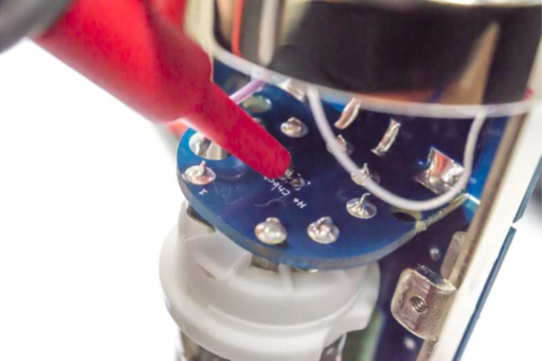
Final Check & First Power-Up
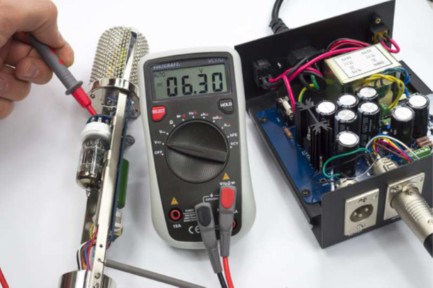
Connect to D-12 PSU via 7-pin XLRMeasure B+ at Pin 1 → Pin 7: expect ~120 VMeasure H+ at Pin 2 → Pin 7: expect ~6.3 V
Measure Bias at Pin 3 → Pin 7: expect ~−1 VCheck POL at Pin 4 in all three positionsSignal and noise verification at the preamp
Connect the fully assembled mic to the D-12 PSU with a 7-pin XLR cable. Power up the PSU.
Warm-up: allow 2–3 minutes for the tube to reach operating temperature before making voltage measurements.
Measure voltages at the 7-pin connector on the mic side (with mic connected):
B+ (Pin 1 → Pin 7): ~120 V DC H+ (Pin 2 → Pin 7): ~6.3 V AC/DC Bias (Pin 3 → Pin 7): ~−1 V DC
Measure polarization voltage at Pin 4 → Pin 7 in each pattern switch position:
Omni: 0 V
Cardioid: ~60 V
Figure-8: ~120 V
If all positions read 0 V, see Errata E27.
Connect to a preamp. Set gain to 50–60 dB. Speak into the mic — expected output requires more preamp gain than a modern condenser; this is normal for this circuit design.
Cycle through all three patterns. Verify each produces output. Any pattern locked in one position — see FAQ.
Check for hum, buzz, or crackling. With the mic fully assembled, the body provides Faraday-cage shielding. Noise that disappears when you touch the body = grounding issue.
⚠️ Do not raise B+ to compensate for low output
If output seems low, diagnose the cause first. Higher B+ can destroy the capsule diaphragm. Fix the underlying fault — verify transformer wiring, check for wiring errors — before adjusting any PSU voltages.
▶ 💡 Expected output level
The D-12 provides approximately 6–8 dB of net gain (about +30 dB in the tube stage, −22 dB transformer insertion loss). This is moderate sensitivity by modern standards. 50–60 dB of preamp gain is typical for vocals at normal distances. This is inherent to the circuit design, not a fault.
Stuck?
Common problems, solved
Before posting on the forum, search here first. These answers are synthesized from the D-12 community thread and build reports.
🔍
No matching questions — try a different search term or clear the filter.
Circuit Reference
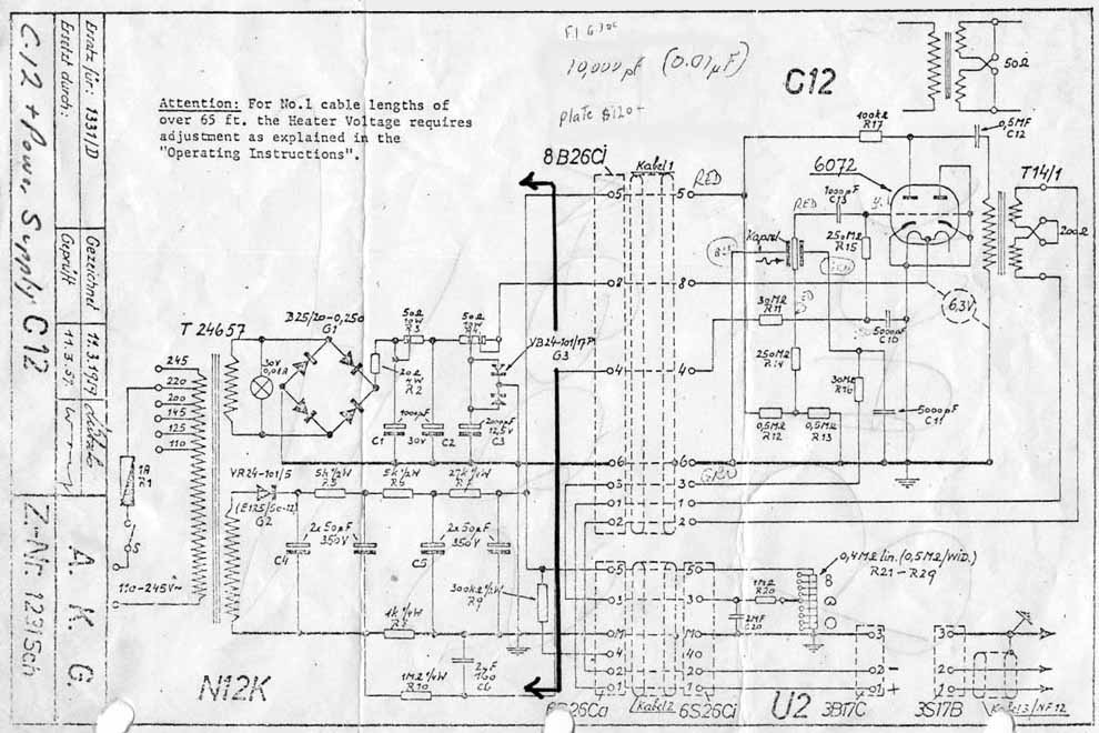
Click to enlarge · D-12 circuit schematic
Key nodes: B+ = ~120 V (plate supply); Bias = −1 V (grid bias); H+ = 6.3 V (tube heater); POL = pattern-switch voltage divider output (0 V omni / ~60 V cardioid / ~120 V figure-8); R11 = 30 MΩ grid-leak; R14/R15 = 250 MΩ backplate bias.
Component List
D-12 Microphone BOM
Components for the microphone PCB. PSU designators are on a separate board — do not mix.
#
Ref
Qty
Value
Description
Part / Notes
Type
D-12 PSU BOM (optional upgrade PCB)
The kit includes a pre-assembled PSU — no soldering required. The D-12 PSU PCB is an optional upgrade for a lower-noise power supply that you build yourself. PSU designators (R1, C1, etc.) are on the PSU board and are independent from the microphone PCB above.
#
Ref
Qty
Value
Description
Part / Notes
Type
Errata
Known issues — read before building
ID
Severity
Description
Action
E26
Critical
Output transformer primary/secondary reversed — very low output and high noise. Installing the Cinemag CM-13114 with primary and secondary swapped gives near-zero gain. The tube's high plate impedance must drive the high-resistance winding (primary, ~1.5 kΩ). Driving the low-resistance winding (secondary, ~300 Ω) instead gives almost no voltage gain.
Before wiring, always measure DC resistance of both wire pairs. Connect the high-resistance pair (red/brown) to the PCB. Connect the low-resistance pair (orange/yellow) to the XLR output. Do not assume by wire color alone — measure first.
E27
Critical
Original Alctron PSU has factory ground wire on Pin 4 (polarization) — pattern switch inoperative. Some Alctron PSU units were assembled with a thin internal wire bridging Pin 7 (GND) to Pin 4 (POL) inside the 7-pin XLR output connector. This was installed for Apex 460 compatibility and must be removed for D-12 operation. With Pin 4 grounded, polarization voltage is pulled to 0 V, locking the mic in omni.
If reusing an original Alctron PSU, open the PSU and inspect the 7-pin output XLR connector. Look for any wire bridging Pin 7 to Pin 4 (may be hidden under heat-shrink). Remove it. After removal: all pattern positions should show correct voltages (Omni 0 V / Cardioid ~60 V / Figure-8 ~120 V) at Pin 4.
E22
Critical
D-12 PSU PCB v1.4 — missing heater jumper renders heater voltage untrimable. The v1.4 PSU PCB requires a solder bridge between two pads labeled "HEATER −" and "GND." Without this bridge, the heater supply LM317 cannot regulate correctly and the heater voltage will read ~11 V with the trim pot having no effect.
On v1.4 PSU PCBs: locate the "HEATER −" and "GND" pads on the PSU board. Install a solder bridge (or short wire) between them. After bridging, the trim pot should control heater voltage normally. Target: 6.3 V.
E28
Warning
Overtightened capsule backplate mounting screw strips the thread. The backplate mounting screw thread is fragile. Overtightening during capsule installation strips the thread, permanently damaging the capsule housing. The damage is invisible until the backplate cannot be repositioned.
During capsule mounting (Step 14), tighten only to firm contact. Do not apply additional torque beyond finger-tight plus a quarter turn. If resistance is felt before the screw is fully seated, stop and inspect for cross-threading before continuing.
Power Supply
Included PSU + optional upgrade
Included PSU — pre-assembled, ready to use
Included in kit
The D-12 kit includes a pre-assembled power supply. No soldering is required.
B+ supply: zener-regulated, nominal ~120 V DC
Heater supply: regulated, trimmed to 6.3 V at factory
Bias: −1 V grid bias
Pattern switch voltage divider: 0 V / ~60 V / ~120 V for Omni / Cardioid / Figure-8
Connect with a 7-pin XLR cable (not included). Verify voltages at first power-up per Step 16. If the included PSU was used previously in a different build, inspect for the Pin 4 ground-bridge issue — see Errata E27.
D-12 PSU PCB — optional upgrade
Optional
The optional D-12 PSU PCB is a builder-assembled replacement that provides a lower noise floor compared to the included zener-regulated supply.
Uses a regulated, lower-noise B+ supply topology
Compatible with both D-12 and D-251 builds (shared PSU design)
BOM: D-12 D-251 PSU 1R0a-1 — supplied separately
The PSU PCB upgrade is built and tested independently before connecting to the microphone. Verify all output voltages match the specifications in Step 16 before connecting a finished mic. The E22 heater jumper errata applies to v1.4 PSU PCBs.
Ready to build?
The complete D-12 kit — body, PCB, component set, capsule, and Cinemag CM-13114 transformer — available at microphonediy.com.
.png)
2.png)
.png)
.png)
2.png)
3.png)