Step 1 / 13 — Before You Start
0%

D-EF47 Build Guide

Step-by-step assembly for the D-EF47 — a tribute to Oliver Archut's EF800 / U47 circuit. Sourced from the original build pictorial. This guide covers the microphone PCB; the PSU guide is published separately.

01

Before You Start

Temperature-controlled soldering iron with fine tip
Temperature-controlled iron — fine tip, ~320–350 °C
Multicore 63/37 solder, 0.61 mm diameter
Multicore 63/37, 0.61 mm — rosin core
Plato flush cutters for trimming component leads
Flush cutters for lead trimming
  • Read this entire guide before placing any component.
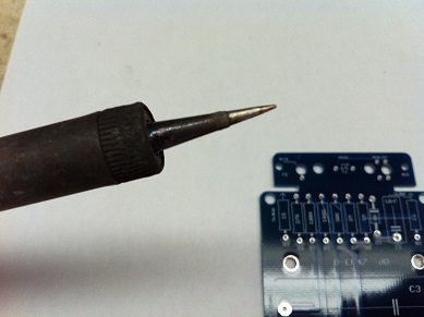
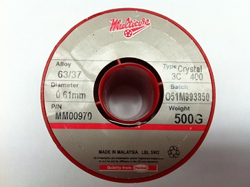
  • Confirm tools: temperature-controlled iron (fine tip, 320–350 °C), 63/37 rosin-core solder (0.6–0.8 mm), flush cutters, tweezers, multimeter, 91 % IPA, lint-free cloth.
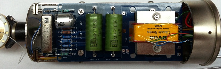
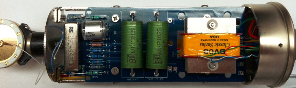
  • This is a high-voltage circuit — the PSU supplies B+ = 105 V and H+ = 5.05 V. Never power the mic from a bench supply or standard phantom power. Use the dedicated D-EF47 PSU only.
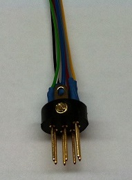
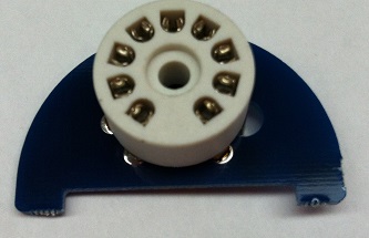
  • Compatible tubes: EF800 (primary), EF802, EF80.
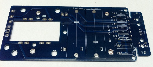
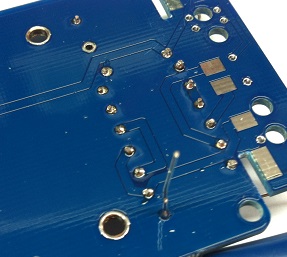
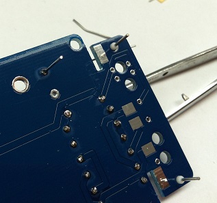
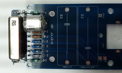
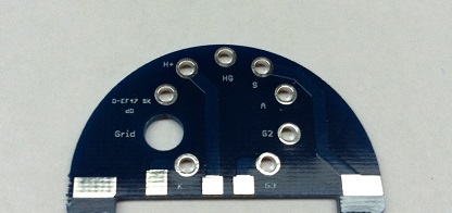
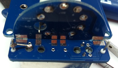
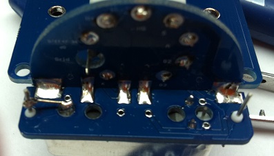
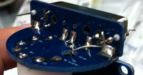
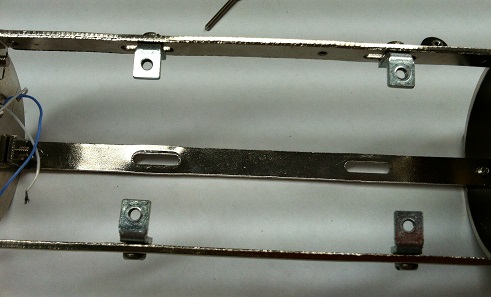
  • The PCB uses two boards that join at 90°: the main D-EF47 board and the smaller semicircular tube socket board (D-EF47 SK). Both are included in the kit.
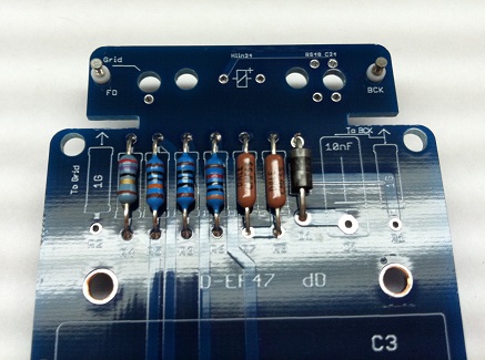
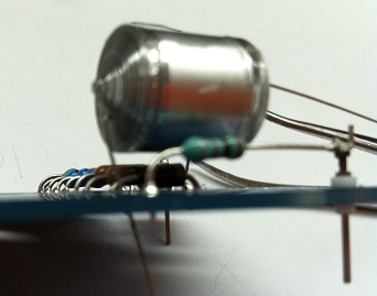
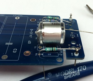
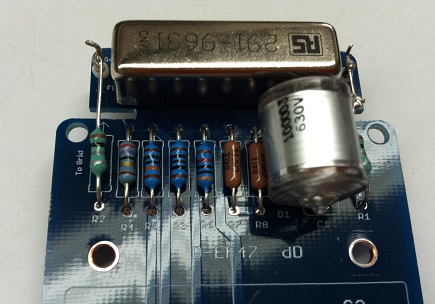
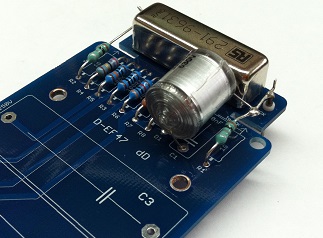
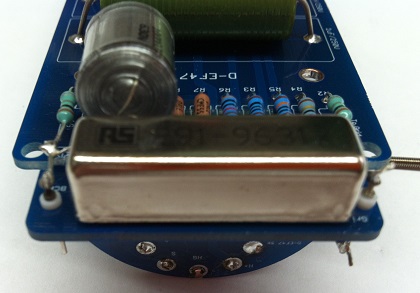
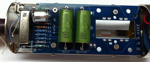
⚠️ Styroflex capacitor is heat-sensitive 
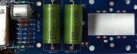
C1 (10,000 pF polystyrene) is damaged by excess heat — damage is invisible at build time but degrades noise performance. An alligator-clip heat sink is mandatory when soldering this component. See Step 4.
02

PCB Overview

Bare D-EF47 main PCB showing component positions and silk screen labels
Main PCB (D-EF47) — rectangular, dark blue. The transformer footprint (T47) is the large rectangular opening at right. C2/C3 output cap positions are center.
7-pin XLR connector with pre-wired leads
7-pin XLR connector. Connected last, after PCB is in body.
  • Identify the two PCBs: the large rectangular main board (D-EF47) and the small semicircular tube socket board (D-EF47 SK). They mount at 90° to each other.
  • On the main board, locate: resistor column R1–R9 (right side), Styroflex cap position (C1, left of resistors), relay position (top edge), output cap positions C2/C3 (center), transformer footprint (right opening).
  • Inspect both boards under good light for any fabrication defects before placing components.
03

Install Resistors

D-EF47 main PCB with resistors R1 through R9 installed in the right-hand column
Diode & Resistor R1–R9 installed. The column includes mixed values — 1G, brown tubular, and standard metal-film types. Follow the silk screen for each position.
Angled view of resistor column with tube socket PCB positioned below the main board
Resistors installed — tube socket PCB (not yet joined) shown below for reference
Solder side of main PCB showing trimmed resistor leads and SMD components
Solder side — trim leads flush after soldering each group
Back of main PCB showing the junction pads between main board and tube socket PCB, with SMD components visible
Solder side of main PCB — junction pads and SMD area near the 90° joint
  • Install all resistors R1–R9 according to the silk screen designations. Verify each value with a multimeter before placing.
  • Pre-form leads to match the pad spacing before inserting — do not force leads through holes at an angle.
  • Solder one leg, verify the component sits flush and straight, then solder the second leg. Trim leads flush on the solder side.
  • The 1G resistor (large brown tubular body, labeled "1G") goes in its dedicated position near the top of the column — handle with care, these are fragile.
Tip — populate lowest-value resistors first Start with the standard metal-film resistors (R1–R8 range), then the high-value 1G resistor last. This keeps the board stable while soldering.
04

Styroflex Capacitor (10,000 pF)

Close-up of the 10,000 pF 630V polystyrene capacitor with its large silver cylindrical body
C1 — 10,000 pF / 630 V polystyrene (styroflex). Silver cylindrical body with axial leads.
Styroflex capacitor installed on the D-EF47 main PCB, standing vertically
C1 installed — the capacitor stands upright between the relay area and resistor column
  • C1 = 10,000 pF (10 nF) / 630 V polystyrene. Non-polarized — either orientation.
  • Heat sink mandatory: clamp an alligator clip on each lead between the capacitor body and the PCB, as close to the board as the lead allows.
  • Solder each lead in no more than 2–3 seconds. Remove the iron immediately when solder flows. Allow full cooling before removing the heat sink.
  • After soldering, inspect the polystyrene capacitor for any discoloration or deformation. Any change in appearance indicates heat damage — replace before continuing.
⚠️ Polystyrene dissolves in acetone and shrinks under heat Never use acetone or aggressive solvents on or near this capacitor. Use only 91 %+ IPA for any cleaning, applied with a brush to the pads — never flooding the component body.
05

Reed Relay (Pattern Switching)

Reed relay close-up showing RS stock number 291-963 on the metal housing
Reed relay — RS B48-1A72-BV631 (48 V version shown, RS stock 291-9631). 24 V alternative: Coto PN 7101-24-1010.
Reed relay installed on the D-EF47 PCB beside the Styroflex capacitor and resistor column
Relay installed — sits adjacent to C1 and the resistor column
Overview of D-EF47 main PCB with relay, Styroflex cap, and all resistors populated
PCB overview after relay installation — resistors, C1, and relay all populated
Underside of main PCB showing output capacitor leads soldered through
Component assembled
Front view of PCB assembly showing relay, Styroflex, resistors, and output capacitors all installed
PCB assembly overview — relay (top left), Styroflex C1, top view
  • The reed relay performs polar pattern switching (omni / cardioid) when triggered by the PSU.
  • Two relay options are supported — select based on your pattern-switch supply voltage:
    48 V: RS B48-1A72-BV631 (RS stock 291-9631)
    24 V: Coto PN 7101-24-1010
  • The coil resistor Rcoil on the PSU PCB differs between the 24 V and 48 V versions — see the PSU BOM notes before assembling the PSU.
  • Insert the relay in the correct orientation per the silk screen. Solder all pins. Inspect under magnification for solder bridges.
Tip — sourcing the relay
The 48 V shielded reed relay (RS 291-9631) is available directly on the order page. The 24 V Coto relay (7101-24-1010) is available from Digi-Key. Both are electrically compatible with the PCB — only Rcoil on the PSU changes.
06

Tube Socket PCB — 90° Assembly

Bare semicircular D-EF47 SK tube socket PCB showing pad labels: H+, HG, S, A, G2, K, G3, Grid
D-EF47 SK — semicircular tube socket PCB. Pads labeled: H+, HG, S, A, G2, K, G3, Grid.
9-pin Noval ceramic tube socket mounted on the semicircular PCB
9-pin Noval ceramic socket mounted on the tube socket PCB
  • First mount the 9-pin Noval ceramic socket on the tube socket PCB: align the index key, press flush, and solder all 9 pins plus any mechanical pads.
  • Insert the tube socket PCB into the edge connector pads of the main PCB so it stands perpendicular (90° angle). The flat edge of the semicircle aligns with the edge of the main board.
  • Tack one corner pad to hold alignment, verify the boards are square, then solder all remaining junction pads from both sides.
  • The resulting assembly should stand on the main PCB without flex. Check for mechanical rigidity before continuing.
⚠️ Critical mechanical joint This 90° solder joint carries all tube heater, and cathode. A cold or incomplete joint here causes intermittent operation or complete silence. Inspect all junction pads under magnification before proceeding.
07

SMD Components on Tube Socket PCB

Top view of the tube socket PCB showing SMD component pads being populated
Tube socket PCB — top view. SMD pads in the arc near the socket base.
Solder side of tube socket PCB showing SMD components soldered to the back pads
Solder side — SMD components on the back of the tube socket PCB
Close-up of solder side showing SMD joints on the tube socket PCB
Inspect all SMD joints — fine tip and controlled heat required
  • The tube socket PCB has SMD pads on its back (solder) side. These are bypassing and filtering components for the heater and cathode lines.
  • Use a fine iron tip (1.5–2 mm) and minimum solder. Apply heat to the pad first, then feed solder — do not feed onto the iron tip.
  • The tube socket is already mounted on this PCB (Step 4). Work carefully to avoid disturbing existing joints.
  • Inspect all SMD joints under magnification before proceeding. A solder bridge on the tube socket PCB can short heater-to-grid or cause oscillation.
08

Output Capacitors (2× MKP 1 µF / 400 V)

D-EF47 main PCB showing two green MKP1839 1µF 630V film capacitors installed at C2 and C3
C2 and C3 — MKP1839 1 µF / 400 V film capacitors (green cylindrical body). Mounted at center of main PCB.
  • C2, C3 = MKP1839 1 µF / 400 V film capacitors (green cylindrical body). Non-polarized — either orientation.
  • These are the output coupling capacitors. The 400 V rating is required to handle the full B+ supply voltage across the capacitor during normal operation.
  • Insert both capacitors into their designated positions (labeled C2, C3 on the silk screen). Press flush to the PCB and solder both leads. Trim leads close.
  • After this step, the main PCB is fully populated. Perform a visual inspection of all components before body assembly.
09

Mounting Hardware

PCB mounting hardware: flat-head M3 screw, two M3 nuts, and two nylon washers
PCB mounting hardware — flat-head screw, 2× M3 nuts, 2× nylon washers. The nylon washers electrically isolate the PCB from the body.
  • Collect the mounting hardware: 1× flat-head screw (M3), 2× M3 nuts, 2× nylon washers.
  • The nylon washers are critical — they electrically isolate the PCB assembly from the aluminum body, preventing ground loops through the chassis.
  • Do not substitute metal washers for the nylon ones.
10

Install PCB into Body

Interior of mic body/cage showing metal L-brackets and body structure
Mic body interior with mounting brackets at each end
PCB assembly installed inside the mic body, with Styroflex cap, relay, and output capacitors visible inside the cage
PCB assembly seated in the body. Output caps C2/C3 (green) are visible; the tube socket PCB faces the capsule end.
  • Slide the PCB assembly into the aluminum body, component side facing outward through the mesh.
  • The tube socket PCB (vertical, with the tube socket) faces the capsule end (top) of the body.
  • Secure the PCB with the flat-head screw through the PCB mounting hole, using nylon washers on both sides of the PCB. Finger-tighten the nut — do not overtighten.
  • Route any connecting wires along the edge of the body to keep clearance for the tube when it is installed later.
11

BV08 Transformer

AMI BV08 Classic Series transformer installed in the mic body alongside the PCB assembly, yellow label visible
AMI BV08 Classic Series — the transformer Oliver Archut specified for this design. Yellow label with "BV08 Classic Series" text.
Top view of mic body showing full assembly: relay, Styroflex, resistors, two MKP output caps, and BV08 transformer
Full PCB + BV08 assembly. The transformer occupies the lower section of the body; the tube socket PCB is at the capsule end.
  • The primary transformer is the AMI BV08 Classic Series — the transformer Oliver Archut personally specified for this design. An AMI T47 may be used as an alternative.
  • Mount the T47 transformer to the PCB or use the off-board mounting adapter. The PCB accommodates the BV08 Classic Series pin layout directly.
  • Connect the transformer primary and secondary leads to the PCB pads per the schematic. Refer to the BV08 data sheet for lead identification (the wires are color-coded).
  • Other transformers can be used with the two-point mounting strategies documented in the original thread. The PCB accepts a variety of transformer packages with the appropriate adapter.
Transformer alternatives The PCB was specifically designed with a footprint for the AMI BV08 Classic Series and AMI T47. A mounting adapter ZIP archive (available in the original build thread) documents two strategies for fitting other transformers.
12

Capsule Installation & Wiring

Vertical view of complete mic internals showing all sections: relay, Styroflex, output caps, BV08 transformer, and capsule at top
Full assembly — top to bottom: capsule end, tube socket PCB (vertical), main PCB with all components, BV08 transformer at base.
  • Mount the capsule in the head assembly and pass the capsule wires through the body to the tube socket PCB.
  • Connect the capsule wires to the pads labeled on the tube socket PCB: Grid (front diaphragm) and G2 or the appropriate back-plate connection — refer to the schematic for exact routing.
  • Keep capsule wiring short. Route the leads along the inside of the body, away from heater and supply lines, to minimize capacitive coupling and noise pickup.
  • Do not touch the capsule diaphragm. Handle the capsule only by its edge or mounting ring.
⚠️ Keep capsule wires away from heater lines The tube heater (H+) lines carry high current noise that can couple into the high-impedance capsule signal. Route capsule wires on the opposite side of the body from heater connections where possible.
13

Final Check & First Power-Up

Completed D-EF47 microphone, fully assembled
D-EF47 complete — assembled and ready for PSU connection and calibration.
  • Before closing the body: verify no solder bridges, no floating leads, no components touching each other or the metal cage.
  • Install the EF800 tube (or EF802 / EF80) into the 9-pin Noval socket. Do not force — the key locates pin 1.
  • Connect the 7-pin XLR cable to the PSU and the mic. Power on the PSU and allow 5–10 minutes warm-up time before any signal evaluation.
  • Calibrate the PSU (see PSU guide): B+ = 105 V, H+ = 5.05 V as per the Oliver Archut schematic. These are measured at the mic test pad on the PCB under operating conditions.
  • With signal present, verify the output is clean and quiet. The EF800 in this circuit is exceptionally low-noise — an audible hiss at nominal gain may indicate a wiring error or incorrect PSU calibration.
⚠️ Use the D-EF47 PSU only Standard condenser mic PSUs and phantom power adapters are not compatible. The D-EF47 requires its dedicated dual-supply PSU (separate B+ and H+ rails). Operating from an incompatible supply may damage the tube or circuit.
Tip — if there is no output
Check in order: (1) PSU calibration — B+ and H+ at correct voltages; (2) 7-pin XLR connector wiring matches the PSU; (3) tube seated fully with no bent pins; (4) 90° PCB joint — check continuity across the junction pads; (5) transformer lead connections — verify correct primary/secondary orientation per schematic.

FAQ

7 questions

Common questions sourced from the D-EF47 build thread.

Which tubes are compatible with this circuit? Tube +
The kit supports three Telefunken 9-pin Noval types: EF800 (primary — what Oliver Archut specified), EF802, and EF80. The EF800 in this circuit is exceptionally quiet. Do not substitute with non-specified tube types — pin assignments and operating conditions may differ.
Can I use a standard tube mic PSU or the Zayance design? PSU +
No. The D-EF47 requires its dedicated dual-supply PSU (separate B+ and H+ rails). Standard single-supply PSUs — including the Zayance design — are not compatible. The PSU is a Passive-2469 topology with special features specific to this microphone.
What are the target calibration voltages? PSU +
Per the Oliver Archut schematic: B+ = 105 V, H+ = 5.05 V. These are measured at the mic connector under operating conditions (tube installed, mic connected). Adjust the 25 K pot (R8 on the PSU PCB) to reach these values.
Which reed relay should I use — 24 V or 48 V? Relay +
It depends on your pattern-switch supply voltage. 48 V: RS B48-1A72-BV631 (RS stock 291-9631) — available on the order page. 24 V: Coto PN 7101-24-1010 (Digi-Key). The coil resistor Rcoil on the PSU PCB changes between the two options — the PSU BOM includes notes on the correct value for each.
Can I use a different transformer? Transformer +
Yes. The PCB footprint is designed for the AMI BV08 Classic Series (primary choice) and the AMI T47. Other transformers can be fitted using one of two off-board mounting strategies documented in the original build thread (a ZIP file with mounting diagrams was posted by poctop).
How long does the tube need to warm up before evaluating sound? Tube +
Allow 5–10 minutes after power-up before any critical listening or calibration. Tube characteristics — particularly plate current and noise floor — stabilize as the cathode reaches operating temperature. For final calibration, allow 15–20 minutes of warm-up.
Is there a difference between the BV08 and the BV8R? Transformer +
The BV8R is a variant that the AMI site mentions as suited for EF800 use. The BV08 Classic Series was the transformer Oliver Archut personally used and sent for this build. Both are electrically compatible with the PCB footprint. Verify lead configuration against the schematic before soldering either version.
?
No matching questions.

Schematic

📄
D-EF47 Microphone Schematic — Rev 1.0 PDF — circuit schematic for the mic PCB. Use this as reference for component values, lead orientation, and capsule wiring.

The schematic was drawn by Poctop. Component reference numbers on the schematic correspond to the PCB silk screen. Note: the PSU schematic is a separate document — see the PSU section.

Components

Mic PCB & PSU PCB

Mic PCB

#RefQtyValueNotesPart #Type

PSU PCB

PSU designators are independent from the mic PCB above. ⚠️ Verify component placement against the schematic, not the silk screen — early PCBs have B+/H+ label errors on R1–R3, R6, R11.

#RefQtyValueNotesPart #Type

PSU

D-EF47 PSU PCB

Required
The D-EF47 uses a dedicated dual-supply PSU (Passive-2469 topology). It provides:
  • B+ — 105 V anode supply (high voltage)
  • H+ — 5.05 V heater supply
  • Reed relay drive circuit (pattern switching)

The PSU PCB build guide will be published separately. In the meantime, refer to the schematic. ⚠️ Verify component placement against the schematic, not the silk screen — early PCBs have B+/H+ label errors on R1–R3, R6, R11.

Ready to build?

Complete D-EF47 PCB kit — mic PCB, tube socket PCB, and hardware. Transformer and tube ordered separately.

Order the D-EF47 kit